Router On A Stick with OpenWrt and Raspberry Pi
We will use a Raspberry Pi and a managed Switch in order to extend the Pi’s Ethernet Port to a LAN and WAN Port using VLANs with OpenWrt. This will effectively turn the Pi into a Router with a WAN port and multiple LAN ports. I will be using a Netgear GS308E Switch (ASIN: B07PDHVZNS), but you could use the following switches as well:
- Zyxel GS1200 (recommended): ASIN B0798PKGFQ (8 Port) or B08K2KKK86 (5 Port)
- Netgear GS305E: ASIN B07PHNTV45
- TP-Link TL-SG108E: ASIN B00JKB63D8, 5 Ports (TL-SG105E): ASIN B00A128S24
 Watch the video on YouTube
Click to view the entire transcript
A router usually has at least two Ethernet ports – in the Consumer segment that’s usually one for LAN and one for WAN. This little Raspberry Pi 2B here only has one Ethernet interface. So what options do we have if we wanted to turn it into a router? We could of course just add another Ethernet interface over USB. Or – we could do the following: We use VLANs and a managed switch in order to extend that one Ethernet port to multiple ports. Our Pi could then have not only two but three or four ports on different networks.
Just before we do that - to make it clear from the very beginning – I am not advocating in any way that this would be a good or viable solution as an Internet or Wifi router for your home. The Pi is difficult to get, it’s very expensive at the moment of making this video in 2023 and there are many limitations which we will look at throughout the video. However, the solution shows nicely how you can extend any device with one Ethernet port to multiple ports using a switch. In other words - that could as well be an old PC or Laptop or thin client for example. It doesn’t have to be a Pi.
Let’s go step by step. First let’s install OpenWrt on the Pi. We could as well do this without OpenWrt – with plain Linux – but – with OpenWrt we have a nice GUI – and also it’s made for routers.
(Installing OpenWrt)
Let’s first browse to OpenWrt.org and select the right image. I klick on the Link for the Firmware selector where I can then chose the Raspberry Pi Model and also the desired Version of OpenWrt. Chose the Squashfs Factory Image or the Ext4 Image. With the Squashfs Image you can be reset to Factory Settings at any time. With the ext4 image that’s not possible. Flash the Image to the SD Card with dd or with the Raspberry Pi Imager. Let me quickly show you both methods. In the imager you would click on “Choose OS”, then scroll down to “Use Custom” and select the img file that you have downloaded from OpenWrt. I did not have to unzip it first. Selecting the gzip file directly did work well. Click on Storage in order to select the SD card that you want to write on. Under Linux this wants to run as root. If you are in the sudoer group then you will just be asked for your password. Klicking on Write starts the process. When it’s finished it will tell you so. Now for dd from the command line. This also needs to be ran as root so I’ll become root quickly. Now just to be safe – I’ll do an fdisk -l in order to list all disks. I don’t want to accidentally erase my hard drive. In my case it’s sdb. Make sure you double check on that one. As dd is just writing bit by bit, I need to gunzip the image file first and then run dd. The infile is the image from OpenWrt and the output file is /dev/sdb plus I chose a blocksize like 4096 for example in order to have dd write larger blocks. Here we go. Smooth. In either case I can now put the SD card into the Raspberry Pi and power it on.
(Logging into OpenWrt)
Once I have connected the Ethernet interface of my Laptop to the Pi, I can then connect to the web Interface on 192.168.1.1. OpenWrt by default acts as a DHCP Server. The default login is root without a password – so I’ll quickly change that under system – then administration in order to get rid of that warning. If I go to network – then Interfaces – I can see the only interface here is the LAN interface. But before we move on with the Pi, let’s have a look at the Switch.
(Configuring the Switch)
I will be using a Netgear GS308E switch. That’s an 8 Port managed Gigabit switch. It’s important to use a managed switch for what we want to do as we need VLAN-awareness. This switch family comes in various sizes. There is a 5 port version which you can buy for roughly 20 Dollars. There are unmanaged versions without the E in the name or POE versions with 5 or 8 ports such as the GS308EP that sells for roughly 80 dollars. TP-Link has a comparable switch family, the SG switches. They have a similar naming convention and also comparable prices really. If you don’t have a managed switch and if you want to buy one, then I can recommend the Zyxel GS1200 in that same price range. It does have additional features such as Link Aggregation plus you can chose the VLAN for the Web interface. I’ll come to that one later. So as you can see – you have the choice.
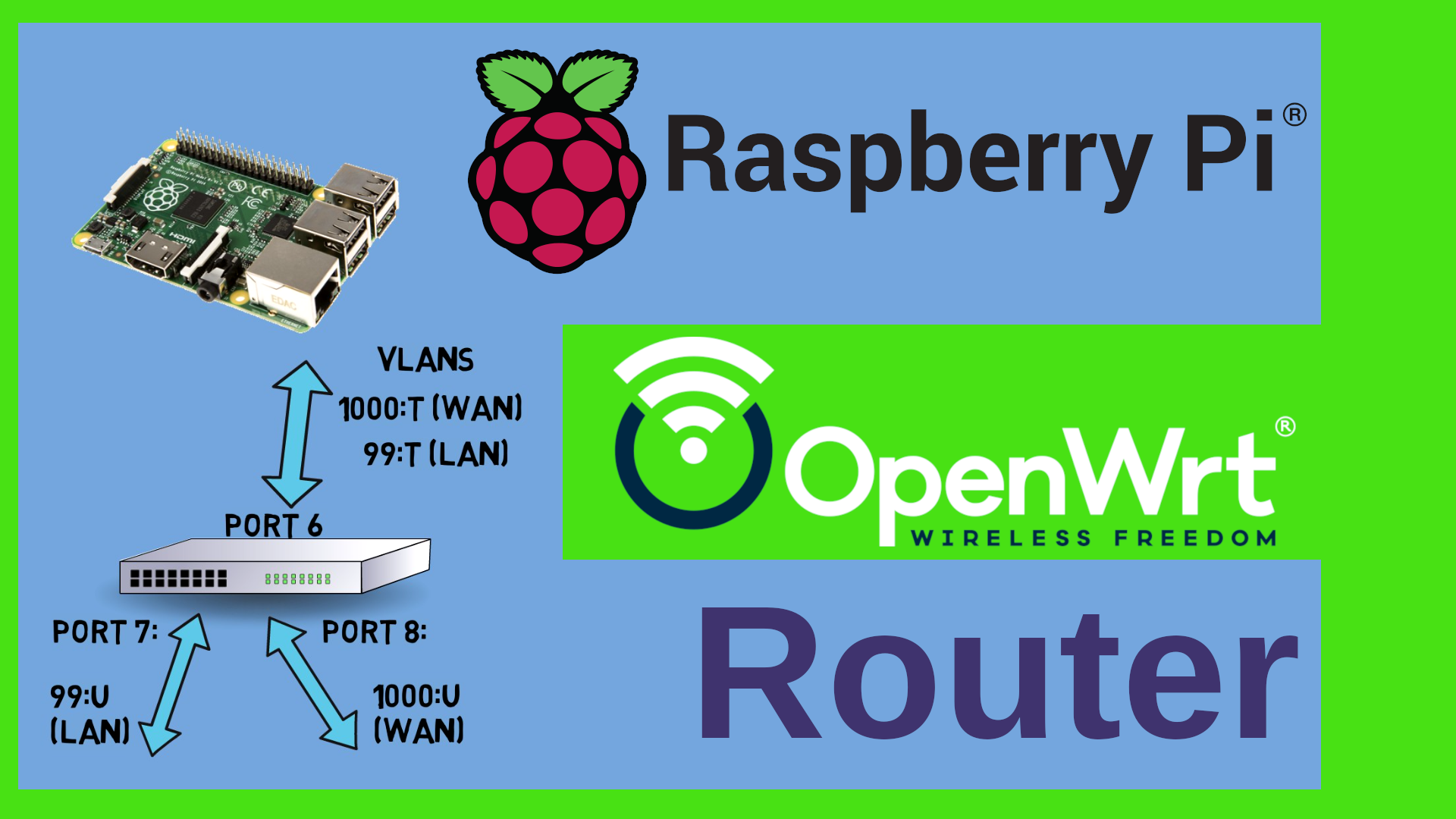
Now let’s configure it. For starters we would need at least three ports here. One Port for the LAN, one for the WAN and one for the Pi itself. By default every port on this switch is untagged on VLAN 1 – let’s change that. I want to use the following VLAN numbers. 1000 for the WAN and let’s say 99 for the LAN. In order to do this, I click on VLAN, then 802.1Q, then on “VLAN Configuration” here under “Advanced”. Here I tick the “Enable” Radio button. As you can see here – all ports are currently on VLAN 1. Under “VLAN Membership” we can see that they are “Untagged” – that means that they are participating in this VLAN but they are not adding a Tag to the Ethernet packets containing the ID of the VLAN. In Cisco terminology that would be called “Port VLAN” as opposed to “Trunk VLAN” for a tagged port. The “U” means that everything for that VLAN will be dispatched to that port and also be stripped of any tag. So first I need to add the VLANs that I want to use. I just type them in under VLAN configuration and confirm with Apply. Next I want to assign the ports to the VLANs under VLAN membership. So let’s say Port 8 is going to be the WAN port and port 6 will be the Pi. Therefore Port 8 will be untagged and port 6 tagged or trunked. Apply. Now the LAN. That’s VLAN 99. Let’s say that should go to port 7 untagged and again tagged to the Pi. We do also need to assign the PVID – the Port VLAN ID to the untagged ports. Why? When a packet comes in untagged, then we don’t know which VLAN it should belong to. The “U” for untagged in the previous screen is relevant for egress – meaning we dispatch the corresponding VLAN to that port. The PVID here is relevant for ingress – for incoming packets that do not have a tag. It’s kind of an assumption we make. If ever a packet comes in on port 8, let’s assume or rather define that it should belong to the VLAN 1000. We would not expect any untagged packets on port 6 as we will configure the Pi to tag everything. So in theory we could leave the PVID at its current value. However – I am not a friend of VLAN 1. So many hardware products have this hard coded, I really don’t want any undefined traffic here. Problem is that I can’t remove the Port 6 from VLAN 1 because it still has 1 as the PVID. So what I tend to do in my network is that I define an additional VLAN ID which will actually never be used. Let’s say 55. So let me add this and then add port 6 to that VLAN tagged. While I am at it I can do this with all other ports as well. Let me add them to VLAN 55 and then set the PVID to that unused VLAN. I’m not changing port 1 for the moment because that’s the one I am connected to. Last but not least I will remove all of them from VLAN 1. You could as well add all those unused ports to let’s say the LAN port by assigning them untagged to VLAN 99 and setting their PVID to 99 as well. The important part is that Port 6 is tagged on everything and that ports 7 and 8 are untagged. Port 6 should be the only port that participates in 99 and 1000 at the same time. This is the port where we will connect the Pi to. Now let’s tell the Pi about those VLANs.
(configuring the VLANs on the Pi)
In LuCi on the Pi I click on Network – Interfaces, then I select the devices tab. Here I have a bridge called br-lan. I will be using DSA and Bridge VLAN filtering here. So edit that bridge, go to the Bridge VLAN filtering Tab and enable VLAN filtering. Now I add VLANs 99 and 1000 and tag them. Save. Very important: Do not click “Save and apply” during the steps we perform here. We first need to do all changes and only then we apply them. Otherwise we will lock ourselves out. If ever you lock yourself out, please do nothing – just wait for LuCi to revert the changes after 90 seconds. So just wait a minute and a half and LuCI will give you the option to revert. Next, let’s add the WAN interface as a DHCP client and of course assign it to VLAN 1000 on the bridge. Just double checking that the “Use Default Gateway” is checked which means that OpenWrt will use this interface as a default gateway. As we called the interface “wan” – it is now already assigned to the “wan” firewall zone. Again. Click on Save BUT NOT on “Save and Apply”. Last but not least we need to tell the LAN interface that it should be on VLAN 99. Let’s edit the interface properties and change the device to br-lan.99 – save. Now we could save and apply but I want to double check everything by clicking on this “Unsaved Changes” icon up here. Yes – we add the VLAN 99, the VLAN 1000, we assign WAN to 1000 and LAN to 99. Looks good. Save and Apply.
Now I will lose Connection. This is expected. LAN and WAN now expect tagged packets. That means that I now have 90 seconds to connect everything to the switch. My Laptop to port 7, the Pi to port 6 – here we go – back in business. Now I can connect the WAN to port 8 – yep – it gets an IP address. Let me quickly see if DNS and the like are working. Network – Utilities and ping Openwrt.org – that works – we are connected.
OK – this has been a lot of click here, click there – what have we done here? Both the Pi and the Switch on port 6 now add VLAN tags to all packets. There are two tagged VLANs – 1000 for the WAN and 99 for the LAN. The switch removes the tags from the packets coming in on port 6 and patches them to port 7 (if the tag was 99) or to port 8 (if the tag was 1000). The other way round, any untagged or “normal” packet coming in on port 7 will be tagged with VLAN 99 and sent out tagged on port 6 – to the Pi. Same for the port 8 with VLAN 1000. We have successfully turned one Ethernet port into two by using tagged VLANs and Port VLAN IDs. Awesome – now we do have a working router with a WAN port and up to 6 LAN or other ports – depending on your switch really. Now here’s two more things that I want to show you and also a couple of remarks with regards to performance and security. Let’s start with security.
(Config Summary)
Here’s again a short summary of the config that we wanted to achieve. If you got lost or locked out at any time, then alternatively you can mount the sd card of the Pi on a Linux Workstation and open the /etc/config/network file – this is what it should contain. I’ll put a copy on Github for you.
(Security remarks)
Using the same wire for WAN and LAN traffic as such is not a big problem really as long as you avoid using VLAN 1 and as long as you avoid untagged traffic. We did that – that should actually be quite secure – at least by home user standards. What can pose a serious security problem though is that switch. The switch has a web interface. And that web interface is bound to the IP address of the switch of course. Now – unfortunately – I can’t tell the switch which VLAN it should be listening on. That means that potentially the web interface of the switch could be bound to the WAN interface. In other words, the Web interface of your switch could be accessible from the WAN. That’s definitely a show stopper for me. I would not recommend using this config as an Internet router. You would of course still be somehow protected by your ISPs router if you connected the WAN interface of the Switch to the LAN interface of your ISPs router, so if you would create a double NAT with a DMZ – a demilitarized zone – between the ISP and the Pi. But still – you have no control which interface the switch would bind its GUI to. That’s sad. The Zyxel GS1200 does NOT have that problem. That’s the reason why I can recommend it. So – again – If I needed to buy a new switch, then I’d rather use the Zyxel.
(Performance remarks)
Now let’s have a look at some performance benchmarks. While everyone is talking about 10 Gbit connections, This Raspberry Pi has a 100Mbit interface. So realistically we can’t get much higher than let’s say 80 or 90 Mbits even with full duplex because we use the same wire for WAN and LAN. I did some tests here with iperf3 and as you can see it’s not only maxing out at 80 or 90 Mbits really, but also there are a lot of retries here in iperf3. Now – that might be related to pause frames created on the switch as I have connected everything to a Gigabit backbone. Now I wanted to make some more tests with dedicated USB Ethernet adapters. In theory I should be able to get to something in the 300 Mbit range with a USB Ethernet adapter. I can’t get higher on this Pi, because it only has USB2. The Rasperry Pi 3 has Gigabit Ethernet but still internally wired to the USB2 controller. So that has more or less the same limitations really. If you want to get close to Gigabit Speed, then you would have to use a Raspberry Pi 4 or any of the more modern versions such as the Compute Module etc. Anyhow, Here is how to add USB adapters. Just plug in the USB Ethernet adapter, then check the Syslog in order to get an idea which driver you might need. In my case it seems to be ASIX, so go over to system-software and search for kmod-usb-net and see if there is a module available for that hardware. I’m lucky, there is one for the ASIX. So let me install it. Checking back in the syslog, I can see that it has now been recognized as an ethernet adapter. Now I can change the WAN adapter to eth1. Or rather add a new interface and disable the old one. Then I’ll do the same game for the LAN adapter. Here I just change the device. Ready to go? Let’s test again. And – as you can see – this is better than before, slightly better bandwidth. Few if any retries, but still we seem to be stuck at around 100 Mbits really. I tried offloading as well but that didn’t help. Looks like the drivers only use one CPU really.
(Additional Configuration)
There is some additional configuration that you might want to do on the Raspberry Pi. For example if you look at the available disk size here, then you can see that the partition is just 104 Mbytes in size even though I have an 8 Gbyte SD card here. We can easily fix this. First I need to ssh into the router, then I’ll update the opkg sources and then install the fdisk software package. The first step is to increase the size of the partition. So let’s get a list of all partitions. This is the SD card apparently. /dev/mmcblk0p1 and p2. In order to resize the partition we launch fdisk on the block device and print out the current partition table. We need to take note of the start sector of this 2nd partition here. Now we delete the partition. Yes – we delete it. No worries, before we write the changes onto the disk, we recreate it. So “d” for delete, partition 2, then immediately “n” for new partition, “p” for primary”, again partition number two, and this is the critical part – we need to fill in the same start sector as before. Keep the end sector because by default this is the maximum size. Now fdisk tells me that there is already an ext4 partition. And I do for sure NOT want to remove this – so No. “P” Prints out the current layout – as you can see, the second partition is now 7.4 Gigs in size. And the start sector is the same like before. So let’s write this by typing “W”. Now we need to resize the file system on this partition. There is a nice article on the OpenWrt Forum that describes how to do this on X86. The procedure is more or less the same on the Pi really. If we scroll down, it describes how to do things on UEFI and the like, it shows the fdisk maneuver which I have just done and here’s the interesting part. Normally we can’t resize the file system if it is mounted. But what we can do is that we create a loopback device to that partition and do the operation on the loop device. Let me give this a shot and just copy paste the code. This fails badly. Apparently it can’t identify the devices properly. So let me do this by hand. First I set up the loop device, then run a file system check, resize the file system to the maximum of the partition and then reboot. Again – remember – 102 Mbytes here. Reboot. And after the reboot I have more than 7 GB available. Ready to install some software on this box. I could as well have taken the sd card out, attach it to a USB reader and do the resize on a different system using gparted or the like.
(Some remarks on Wi-fi)
We haven’t talked about Wifi yet. This Raspberry Pi 2 does not have any Wi-fi. Of course I could use a Raspberry Pi 4 – or I could add Wifi hardware over USB. But – let’s face it – none of these makes a good access point. The drivers and the hardware are designed to be used in STA mode – as Wi-fi clients. Just because there is a linux driver for a Wifi module, does not mean that it is great in Access point mode – look, you would not get features like MU-MIMO or the like – plus, the total amount of money that you need to spend will be much more than let’s say the price of a really good Wi-fi 6 router such as the Belkin RT 3200. You can get that one at around 80 to 100 Dollars and it’s a really nice device.
(What can we use this for?)
So -whats left? What can we use this for? In my opinion the real strength of this setup as opposed to a commercial Wi-fi router for example is the amount of RAM that we have available plus the fact that we can extend the file storage considerably by adding a larger sd card or an external ssd drive. So I would rather see this as an application server that needs multiple Ethernet ports – VOIP for example. You could add asterisk or yate as software packages and run the thing as a PBX. You could hook up multiple phones to it and it would really not use a lot of energy to run. But still – I would not go and buy any of that equipment new at the current price points. If you have them in a drawer or if you plan to use them for something else in the future – then maybe go for it. In one of the next episodes I will also show you a possible application of a Raspberry Pi with OpenWrt as a phone tethering gateway. We will not even need a switch for that. So – here’s another reason to stay tuned to the channel right? Please do leave me a comment on YouTube! Many thanks for watching! Stay safe, stay healthy, bye for now.