The VLAN Konfiguration has changed in OpenWrt 21.02 - Bridge VLAN Filtering and Distributed Switch Architecture (DSA)…
The VLAN Konfiguration has changed in OpenWrt 21.02 - Bridge VLAN Filtering and Distributed Switch Architecture (DSA) change the way we configure the network segmentation in a Guest, IOT and LAN Network.
 Watch the video on YouTube
Commands typed or used in this video:
cd /etc/config
cp network network.bak
opkg update
opkg install diffutils
while true; do clear ; diff network network.bak ; sleep 1 ; done
to check if IP4 forwarding is active:
cat /proc/sys/net/ipv4/ip_forward
(0: not active, 1: active)
to disable forwarding (does not survive reboot):
echo "0" > /proc/sys/net/ipv4/ip_forward
to survive reboot, add
into the /etc/sysctl.conf file
The Linux Kernel DSA Documentation is here: Linux Kernel doc
Click to view the entire transcript
Many of you left me comments for my OpenWrt VLAN videos. Many thanks for that. The general feed back was „Where have the VLANs gone in OpenWrt 21 ? Everything has changed.“ Well, surprisingly enough – the VLAN functionality in OpenWrt 21 has not changed at all – it still works exactly the same like in Version 19, but two things are new in OpenWrt 21 – one is called Distributed Switch Architecture or DSA – which in fact changes the way we configure the switch portion of our OpenWrt devices and replaces swconfig – and the second profound change is bridge VLAN filtering. Stay tuned.
(intro)
Guys, here is the breakdown of this episode. Do not hesitate to use the chapter markers if you want to skip or fast forward. For those who have seen the previous videos, we do the Version 21 configuration at this time marker here. Many thanks.
First let’s quickly recap what a VLAN is. A physical Ethernet LAN is basically a wire or cable. Data is sent over that wire in packets. Devices on the Ethernet are identified with MAC addresses. So a typical Ethernet packet would look like this. We have a small header, then the source MAC address and the destination MAC address, some more information and then the payload, so the data that we want to transmit. Plus a checksum at the end. This way every switch in the network knows where to send the data to.
If we want to segment our Network let’s say into a guest zone and a LAN zone then we would hence need two wires. One Wire would go to the Guest WiFi access point and the other one to the LAN access point here. Or – we can do with one wire running two virtual LANs, two VLANs. Rather than pulling a second wire we use one wire and identify the packets inside with an additional tag in order to figure out which LAN they belong to. In essence it’s like putting a yellow or red or blue post it on the packets saying the blue packets belong to guest and let’s say the yellow packets are for the LAN. Of course we don’t do colors here but rather bits and bytes which we just insert into the packet here. A VLAN aware device like a managed switch or an OpenWrt Access point can then receive those packets and dispatch them to either a physical Ethernet port or to a separate WiFi Network. Just like we did in the Guest Wi-Fi video. In case you haven’t seen it – here is a link.
Another way of thinking of VLANs is this: On your router you have physical Ethernet ports. You can plug in a wire to those. With VLANs you can create multiple virtual ports on one physical port. You can do pretty much everything with such a virtual port. You can even connect a virtual port to a physical port or to a Wifi.
On Linux – you remember – OpenWrt is Linux - this can easily be done by defining interfaces that are attached to a physical interface like eth0 for example. If I wanted to call my VLANs 21 and 56 then I would create interfaces called eth0.21 and eth0.56 – that would tag the packets on one VLAN with 21 and with 56 on the other.
We have seen that a VLAN can be used to run multiple networks over one wire or cable. The packets are assigned to the right network by an additional identifier that is inserted into the Ethernet packet. When a VLAN aware network device is attached to a physical device such as eth0 on linux, one can define it just by appending a dot and the VLAN number. Let’s see how to define those in OpenWrt.
So – I told you in the beginning that this has not changed from Version 19 to Version 21. Let’s have a look at Version 19. In my last videos I showed you how to do that in the switch menu. We went to Network – then switch and klicked on “add VLAN” and then we selected the parameters such as the VLAN ID and the ports which we wanted to have in the VLAN either tagged or untagged or not participating at all. This actually did a couple of things. It created the eth0.x interface and then updated the switch configuration to reflect the port assignment. So we defined the VLAN and we defined the switch configuration. Two distinct things here. The VLAN definition only tells the system to add an interface and tag packets. The switch configuration tells the system which VLAN has to be dispatched or distributed to which Ethernet port at the back of the device. The “proper” way of just defining the VLAN interface would have been to actually go to network –
then interfaces,
click edit on the desired interface,
then go to the “Physical Settings” tab
and then select or create the interface where we want to have the VLAN on and type it into the custom field down here directly. For example if I type eth0.123 that would create a VLAN 123 aware network device attached to eth0.
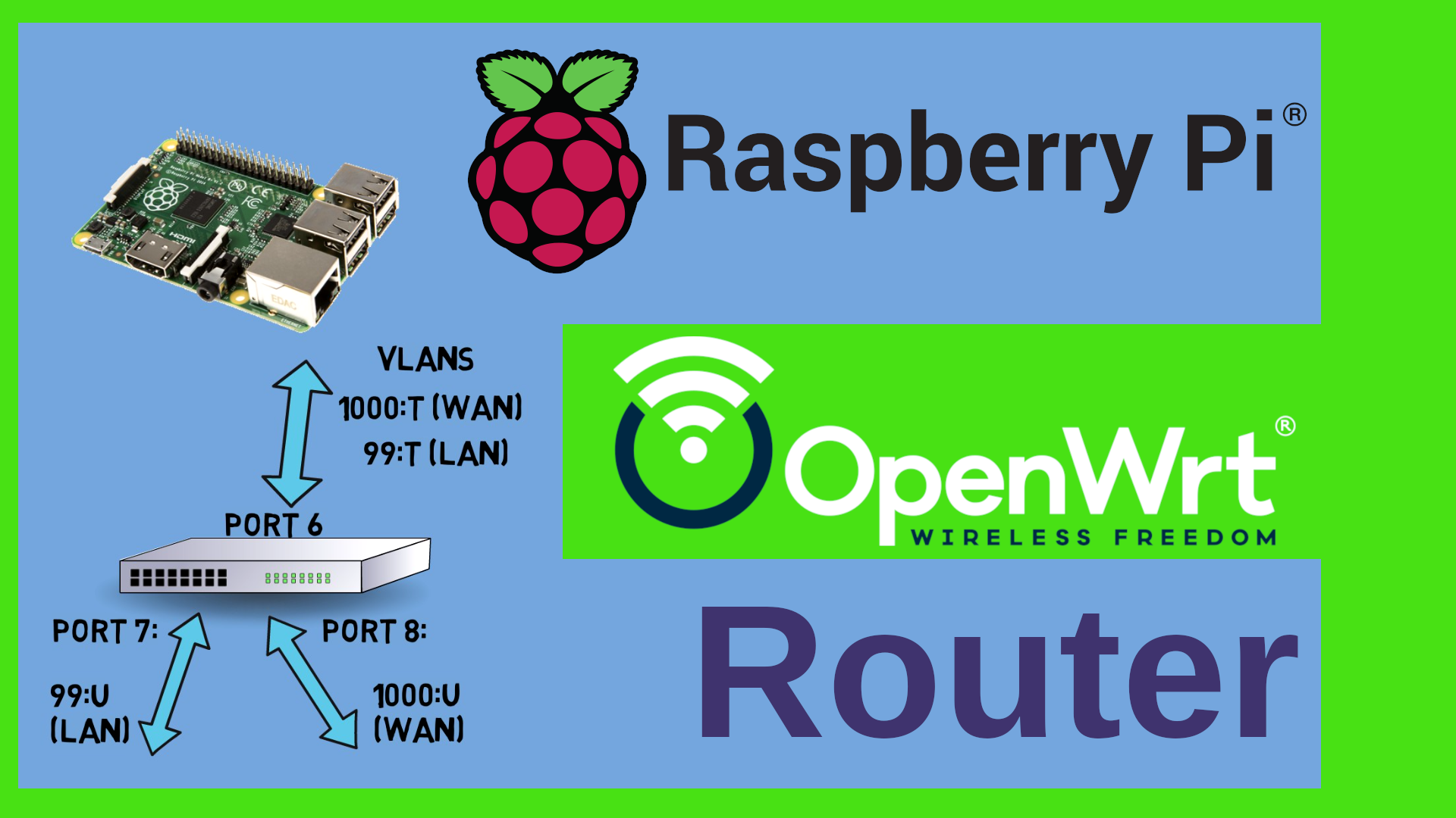
We haven’t told the switch what to do with it or in other words – which port of the switch should actually use that VLAN – so why would we want to do it that way ? Well, think of hardware that does NOT have an integrated switch, such as your laptop or a raspberry Pi or a virtual machine or a container. You could in fact use VLANs on those devices and then attach a managed switch which would take care of the tagging and dispatching etc.
So we have seen that the Network interface and the switch are two distinct parts of our Wifi-Router or generally speaking of our device. We know how to define VLAN aware devices and we know how to dispatch or distribute the VLANs across the ports of our switch. We also know that there are devices that do NOT have switch hardware, such as Raspberry Pis or Virtual Machines. That actually was the buzzword for a – CALL TO ACTION – I need you to get involved please. I have seen that there are a couple of videos here on YouTube about turning a Raspberry Pi into a router. There are also some about VLANs on the raspberry Pi. However, I found that they are either kind of klick here, klick there style without really explaining why or they tell you to use a USB Ethernet device. So here’s my question – would you be interested in seeing a video on how to use OpenWrt on the raspberry pi ? Presumably together with VLANs over a managed switch. Or maybe we can use it as a VPN gateway with Wireguard or I could think of integrating PiHole or Adguard. Let me know what you think. The same question can be asked with regards to virtual Machines – that means using OpenWrt with VLANs inside let’s say Proxmox – let me know if you would like to see anything of that kind. Please do leave me a comment! Thanks guys ! Let’s get back to OpenWrt 21.
This device menu with the custom interface option still exists on OpenWrt 21. So we can do exactly the same like we did on Version 19 here in version 21. Or – there is a more comfortable way to do that on this new devices tab here. If we click on “Add device configuration” then we can select VLAN 802.1Q as the device type, select a base device, for example eth0 and specify the VLAN ID.
You can see the device name that would be created here.
while true; do clear ; diff network network.old ; sleep 1 ; done
Actually let me try something here. I want to show you the changes in real time. The configuration of the network devices and interfaces which is read by OpenWrt at boot time is stored in the file /etc/config/network. I have ssh’d into the router, moved into the /etc/config folder, and I have taken a copy of that file. I just need the software package diffutils installed in order to have the diff command available. With this small one-liner here I am monitoring the changes of the file compared to the copy that I have just taken. That will make it clear what actually gets defined when we do changes in luci here. First I define the VLAN device in the device tab. Hitting save and apply creates that config device section in the file. On the command line we would do UCI commit. That actually saves the configuration. You can see the name, type and vid defined here. When I define the device on the interface then you can see those changes added in the config interface section in this option device line here.
What happens if I reset the VLAN device config ?
It disappears in the config file but is still listed in luci. So it is kind of an implicit configuration as opposed to an explicit definition in the first case. Both scenarios will work. Let me do the interface definition on Version 19 here and as you can see it is kind of the same result just the option name is not called device but rather ifname.
We have just seen that we can define VLAN aware network interfaces in exactly the same way on OpenWrt versions 19 and 21. Now what HAS changed is how switch ports are presented to the user. In OpenWrt 19 we had the switch menu and could tag and untag the ports there. In OpenWrt 21 each port of the switch is actually shown as a network device, in this case lan1, lan2 and wan. So each of these devices corresponds to a port on the switch. This is called distributed switch architecture or DSA. If you want to know more about DSA and why it had been introduced then check out the Linux Kernel documentation. I’ll put a link into the description. Just so much that with DSA each port of the switch is now shown as a separate network device.
Another thing that has changed is the fact that when we create an Interface such as GUEST or IOT or LAN, in Openwrt 19 we could say – this device is a bridge – directly on the interface. We could then select multiple devices that should be on that bridge from the dropdown in the physical settings tab. In OpenWrt 21 we don’t have that option any more. Here again we define a bridge on the devices tab under Network- Interfaces. The device type is “Bridge device” and the Ports of that bridge can be selected in the Bridge ports dropdown. By default you should at least have a br-lan bridge that bridges all the lan ports together of course.
Cool – we already know a lot of things here. We know what a VLAN is, we know that there is a switch part and a network interface part in our system and we know how they are defined in the GUI. Now with this knowledge let’s see how we can implement the GUEST-IOT-LAN segmentation from the earlier videos in OpenWrt 21 – for this we will use the second new feature which is called bridge VLAN filtering.
I want to define the following VLANs – 3 for the IOT network, 4 for the GUEST network and 99 for the LAN. I want to have all of them tagged on let’s say the lan1 port, I then want to have let’s say LAN on the lan2 port of the switch untagged. The wan port will remain the wan port connected to my ISP. I also want to have three Wi-Fi Interfaces attached to each one of those VLANs. So if a guest connects to the guest Wi-Fi then they should be on the guest VLAN and not see anything in my LAN. In the second step I will attach a second Access point to the lan1 port which covers let’s say the 2nd floor of my house and that should of course also have all three Wi-Fi’s. Guys, for the firewall configuration of this please see my earlier video . Link up here. Let’s go.
The first thing that I do is that I define the bridge. By default all lan ports are bridged together. We will keep it that way and do the VLAN filtering later. Let’s go to Network – Interfaces – Devices tab – select the br-lan and click on configure. If there is no bridge, then click on “Add device configuration” down here and select bridge device as the device type and let’s call it br-lan. On the General device options tab make sure that the lan1 and lan2 port are selected in the bridge ports dropdown. If you have more lan ports then you can add them of course. Next, let’s select the “Bridge VLAN filtering” tab. Here we need to tick the box “Enable VLAN filtering” of course. Now we add the VLANs. We just click on Add three times and then let’s review the settings. Change the VLAN IDs to reflect the numbers which we want to use, so 3, 4 and 99. Tick the “Local” box next to each VLAN – I’ll explain that in a second. While you do this please make sure that your laptop or PC where you do that on is actually connected to the port that you want to have untagged on the LAN, in my case that’s lan2. Very important, otherwise you will be locked out.
Quick remark here – if ever you lock yourself out – the easiest way of getting back in is to – do nothing. If the connection to the router is not re-established within 90 seconds after having clicked “Save and Apply” then Luci will revert the changes. So don’t click, unplug etc. Just wait a minute and a half and you should be back in business. Might be a life saver ;-)
I want to have all VLANs tagged on the lan1 port – this is the port where we will connect the second access point later – so I select “egress tagged” on all VLANs on that lan1 port. The VLAN 99 is my internal LAN so I set the lan2 port to “egress untagged” and also I select the “primary VLAN” tickbox – or “Port VLAN” as it should be called or as it is called – that’s actually the PVID on many switches. Do NOT click save and apply yet – we will need to let the LAN interface know about the new VLAN first. But first let me explain these settings.
We need to take two aspects into consideration here: The first one is ingress vs. egress and the second one is tagged vs. untagged. When we select “t” or “egress tagged” on a port then this means that packets that we send to the VLAN 99 will also be sent out to that port. They will be kind of “dispatched” or “distributed” to that port. Outgoing – hence the word egress. The “t” means that we actually write the VLAN tag into the Ethernet packet. A non-VLAN-aware device would in fact not know what to do with such a packet, so we need a VLAN-aware device such as a managed switch or of course our access point at the other end. If we select “u” for “egress untagged” that means that we also write to that port but we do not add a VLAN tag. You could then attach a normal PC to that port and it wouldn’t ever know that it’s on a VLAN. In simple terms – if you have multiple VLANs going over a cable and you want to connect two switches or access points etc. then use tagged. If you just want to attach a laptop or PC to that port then assign it to one single VLAN and select “untagged”. So “untagged” actually means that we are assigning this single port to that VLAN without letting a connected device know that there is actually VLANs involved here. So far for egress. But what if a packet comes in ? How do we know which VLAN it belongs to ? Of course if there is a tag in the packet then we can assign it easily. But how about untagged packets ? This is what the PVID – the primary or port VLAN ID it should rather be called - does. On this lan port 2 we have set this on the VLAN 99. So every packet that comes in untagged will be assumed to go to VLAN 99.
Perfect. Let’s save. Again - don’t save and apply yet. What happened here is that three new devices have been created. Br-lan.3, 4 and 99. So that’s a big difference compared to OpenWrt 19 – it’s not the physical interface such as eth0 that gets the VLAN id but it is the bridge. Next step is to actually assign that bridge to interfaces. And we need to do this before we apply, otherwise we will be locked out. So let’s go to the Interface tab. Click on edit next to the LAN interface. You can see that the Device is set to br-lan – we need to change this to br-lan.99 because our LAN will now be the VLAN 99. Now we can save and apply. Alternatively we can click on that “unsaved changes” icon in the upper right corner here and review the changes and click “Save and apply” there.
If everything went well then you should be reconnected to your device. Just now you are on the VLAN 99 – but you don’t notice because the port that you are connected to is set to untagged. If you connected your PC to the lan port 1 you would not be able to connect.
Perfect. This showed the first big change in Version 21 – VLANs can be filtered on a bridge rather than on the physical device. First we bridge all the switch ports and then we tell the bridge where to assign the VLANs to.
Actually, shall we quickly compare the Version 19 switch tagging to the version 21 bridge vlan filtering from a config file perspective ? Let’s monitor both network configs on this Version 19 and this version 21 router.
First the switch on Version 19.
Then the bridge on Version 21.
Now the interface on Version 19.
And the interface on Version 21
So you can see here that the config option is called switch_vlan in version 19 and bridge-vlan in version 21.
Awesome – now let’s add the other interfaces and the WiFi interfaces. Click on add new interface for each one of them, select the br-lan.x device to be the physical device and assign it to the right firewall zone. Also we want each one of them to act as a DHCP server on different IP address ranges. Again – firewall setup is in an older video. Next we go to Network-Wireless and create the corresponding wireless settings. Now here is another change in OpenWrt 21 – in order to assign the WiFi to the right network you need to open that dropdown box here that reads “Network” and tick the box next to the right network. Guys, for Wireless setup see my two videos about WiFi fast roaming and the other one about how to add a second Access point to an existing network – the links are up here again and in the description. Thanks.
Cool. That’s all on the first router. Oh – hang on – you remember that I told you to tick that “local” box next to the VLANs in the bridge VLAN configuration ? Let’s see what happens if we don’t do this. Let me add another VLAN 55 here and NOT tick the box. As you can see, no br-lan.55 has been created, so we can tag or untag that VLAN on the switch but we can not use it locally on the router to create an interface. That’s the difference.
Now we know so many things – how to define the VLANs on the bridge, how to tag or untag them on the bridge, we know how to assign Interfaces to a VLAN and we know how to hook up W-Fi to them. Let’s move to the second device now.
The second router should act as an access point only – a “dumb” access point as it’s often called in the OpenWrt forums. That means that it should NOT act as a router and NOT serve IP addresses over DHCP and also it should not have a firewall. The basic steps are actually outlined in this older video here – how to extend a Wifi to a second access point so I will not go over all of them. Just the high level overview here. On the VLAN side the configuration is quite similar. In my case I want to use the wan port as the uplink to the main router so rather than having everything tagged on lan1 I’ll move that to wan – but it doesn’t really matter – the wan port is just another switch port – very much like the lan ports – and we are totally free to assign it to one VLAN or the other. In fact, naming it lan or wan is just a convention. I could as well call them Fritz or Hans or Otto.
Let’s remove the wan and the wan6 interface and then go back to the br-lan bridge, add the wan port and tag the port there accordingly on the Bridge VLAN configuration.
Once this is set up then the final result should look like this: three interfaces, again called GUEST, IOT and LAN on br-lan.4,3 and 99. If we set those interfaces to be DHCP clients then each one of them should get an IP address from the router out of the respective IP address range. We set up the Wi-Fis with the same SSID and passwords like on the first one but you may use different channels here. Again – that’s very well outlined in my WiFi fast Roaming video. Actually I have a whole playlist of videos about OpenWrt – the link is up here. You might want to bookmark that or actually subscribe to my channel and check out the channel page. All links are in the description as well.
Cool. Now we have a real network. We have a main router with access to the internet, we have three VLANs going over one single wire to a second access point which extends our three Wi-Fi networks for example to another floor in the house.
Once we have checked everything there are however a couple of things that we should do on the access point for security reasons. The access point still thinks that it should act as a router. As we have no firewall here that means if someone changed his or her default gateway to be that access point then they would actually potentially be able to route from one network to the other. In order to prevent that we can do two things:
First, we disable routing on that access point by setting the ipv4 forwarding flag to 0.
Second, we can also remove the IP addresses from all but one interfaces. If there are no IP addresses on that device then it can’t route. You need to keep one however in order to be able to access luci. We do that by setting the protocol to “unmanaged” on the IOT and GUEST and just keep dhcp client on the LAN interface. Now we can still access luci over the LAN address but the access point has become invisible from an IP standpoint in the other networks.
Yet another tip here – don’t use VLANs 0, 1 and 2 – they are hard coded on some devices for LAN and WAN and could also potentially present a security risk.
So – let’s sum this all up. Here is what we now know about VLANs and so on in OpenWrt 21:
First – VLANs can be explicitly defined as VLAN 802.1Q devices under Network-Interfaces then device tab or implicitly on the Interface by typing in the device name into the custom field.
Second – the Distributed Switch architecture DSA shows every port of the switch as a network device, for example lan1, lan2 and wan
Third – VLAN filtering can be done on the bridge by selecting the “Bridge VLAN Filtering” tab. This will generate devices like br-whatevername.x
Last but not least – we know how to attach interfaces and Wi-Fi’s to those VLANs and we know how to do basic security on the access point.
Awesome – that’s pretty much it – Oh – maybe one last thing. At the time of making this video, that is in December 2021, not all architectures are using the Distributed switch architecture DSA. Some of them still use swconfig, that means the “old” way of assigning VLANs to switch ports. One example is the Archer C7, a very popular router for OpenWrt. One of the reasons is that on devices with multiple Ethernet cards, like eth0 and eth1 in the Archer C7, currently there is no way with DSA to assign the switch ports to one or the other interface. So I guess we will just have to wait on those. I’ll see if I can find a page on the OpenWrt web site that summarizes the supported architectures and put into the description. You will actually have to decide if you only use one card and DSA or if you want to use VLAN distribution to the switch the old way.
Guys – that’s it for today, many thanks for liking, subscribing and sharing the video with others. Please don’t forget to leave a comment. Many thanks for watching – stay safe, stay healthy, bye for now.