DIY Wi-fi Mesh with batman-adv and OpenWrt for Everyone!
DIY Wifi Mesh for everyone with commodity Hardware and Free and Open Source Software OpenWrt! The B.A.T.M.A.N. advanced protocol can be used to build a mesh of virtually any size ! Wired and Wi-fi !
 Watch the video on YouTube
In this episode we will build a Wi-fi mesh with 10 nodes in order to serve W-fi on 3 SSIDs everywhere in the house. I will use six triband mesh systems from Asus (Lyra MAP AC-2200, ASIN B072XT1CHN) in order to build a transparent fast-roaming (802.11r) Wi-Fi mesh (802.11s) network with Multiuser MIMO (MU-MIMO). Vendors like vilo, Amazon (eero), tp-link (deco), linksys (velop), asus (zenwifi), huawei (wifi mesh 7) are marketing mesh systems. In my oppinion however, the BEST MESH in 2022 is the one that you build on your own ;-)
You can download the batman-adv luci package here: OpenWrt package on Marc’s Github
Click to view the entire transcript
Here’s what we will do today: We will build a Wi-fi Mesh with OpenWrt. I bought a couple of these ASUS Lyra mesh access points here. Got them real cheap on eBay. I paid 25 bucks each. Great Wave 2 Wifi 5 devices with 3 radios inside. MU-MIMO, Mesh and everything. Difficult to get however – they are end of life from a sales perspective. I flashed them with OpenWrt and built a Wi-fi Mesh along with some more Wi-fi access points that would otherwise collect dust in a box. Like two of these Archer C7’s, a Xiaomi Mi router, a Belkin RT3200 and some custom built devices. My Wi-fi mesh is as big as I could build it – I actually spread those Access points everywhere in the house and also in the garden in order to make it a bit larger. Over all I have roughly 10 nodes in the Mesh. On the mesh I have three different Wi-fis which are called M-IOT, M-GUEST and M-LAN.
If you have read the title or the description of the video you might wonder – what has B.A.T.M.A.N. to do with all of this? First off – this is NOT about the guy with the deep voice who runs around in tights – we are talking about a network protocol here. More specifically a MESH protocol. B.A.T.M.A.N. is short for “Better Approach to Mobile Ad-Hoc Networking”.
Why would we need or why would we want that B.A.T.M.A.N. protocol? Maybe you have seen my other videos about Wi-fi Mesh – in the first episode I showed you how to build a Mesh with OpenWrt. It’s actually really easy and only takes minutes or an hour at most I would say. If you only have let’s say three Wi-fi mesh nodes and one single Wi-fi name or SSID as it’s called, then you don’t need anything else – you’re fine with the basic functionality of Mesh in OpenWrt. If you can run Ethernet cable between your Wi-fi access points then you don’t even need a Mesh at all – you’re much better off using a wired installation like I proposed in this video here. Link up there. So when would batman advanced be a good choice for you then? It does make sense if you have one of the following use cases:
Maybe you want to go BIG – so by BIG I mean really big – like rather than planning for 3 or 5 nodes in the house you want to build a MESH for your neighborhood or for the valley or the town or city with potentially tens or hundreds of nodes. In this use case you would probably have multiple nodes that provide internet access and hence you would need a protocol that can figure out which node has the best connection to the internet. Definitely a use case for batman advanced. And – it’s proven that it works. Have a look at the German Freifunk community. They are using it all over the country in meshes with up to hundreds of nodes.
Second use case – and that’s valid for any size – you have multiple Wi-fi names or SSIDs- such as IOT or guest or Wi-fi’s for different groups of users – in this case you would need to be able to use VLANs over the mesh. In my second Wi-fi Mesh episode we had used gretap for that. But gretap is a point to point protocol. Batman advanced can do VLANs over the whole mesh. By default. Out of the box. And it’s actually very easy. It can be done in five minutes.
Third use case – maybe your mesh is not all Wi-fi. Look at this diagram. We have a three node Wi-fi mesh here that is connected to an Internet gateway. And maybe we are extending the mesh on the “other” side of the gateway. And maybe we have two or three of these. In a non-batman mesh the traffic would go off mesh in the middle. In a batman advanced installation the mesh could go over the whole network. Including the wired part.
Actually there’s a fourth use case – and that is an aspect of the batman protocol that is in my opinion often under-evaluated. As the B.A.T.M.A.N. advanced protocol can do VLANs – it can do something quite exciting. It can actually transform your whole network into a giant managed switch. You could plug in devices over wire or Wifi or mesh into any of the VLANs at any point. So you could in fact use the B.A.T.M.A.N. advanced protocol if you want to do VLANs but you don’t have a managed switch. Very exciting.
Cool - we have seen that the B.A.T.M.A.N. advanced protocol basically solves two or three shortcomings of a basic Wi-fi Mesh. First – it is a protocol that helps solve the basic challenge that you have in a mesh as opposed to a point to point network – that is helping the packets to find their way to the right counterpart. A little bit like the “traveling salesman” problem really. And second – as it can do VLANs – we can have multiple Wifi names go over one single mesh.
Now let’s see how we can get hold of it and how we can install it. It only takes five minutes really. If you already have your OpenWrt configured like in one of the last episodes then you can skip the next chapter and fast forward to this time marker here. If not, then I will show you real quick in the next chapter how to prepare your OpenWrt Router and Access point for mesh. I won’t go into every single detail but just outline the necessary steps. For a detailed explanation please watch the first episode.
The blue print is as follows: We will have three wifi’s, called M-IOT, M-GUEST and M-LAN. Each one of those has their own network and firewall zone and will be replicated, bridged or repeated if you want on all other Access points over the Wi-fi mesh.
Alternatively we may have something like this: If our Internet gateway does not have Wi-fi then we may as well include a wired section in the Mesh. That’s a big advantage of using batman advanced. You don’t have to go off mesh at the intersection between wire and Wifi if you have wired sections. In this example the middle part would still be part of the Mesh but rather than going over Wi-fi it would go over Ethernet or maybe even a VLAN.
First let’s see the steps that we need to do on all routers and access points that participate in the Wi-fi portion of the Mesh. In order to be able to use the Wi-fi as Mesh point, we need a specific version of WPAD. For example wpad-mesh-openssl or wolfssl. So let’s go to system-software and then install one of those. Now we can go to network-wireless and click on Add next to the desired radio. I use a dedicated 5GHz radio for that as my Lyra’s have two of them. Down here in the Interface Configuration I select 802.11s for the mode, I’ll give it a name in the Mesh ID field, but I leave the network blank for the time. We’ll attach this to the batman network later. In the Wireless Security tab I select WPA3-SAE and type in a secret key. That’s it for the moment. If you already have a mesh like this then you would see the existing nodes down here.
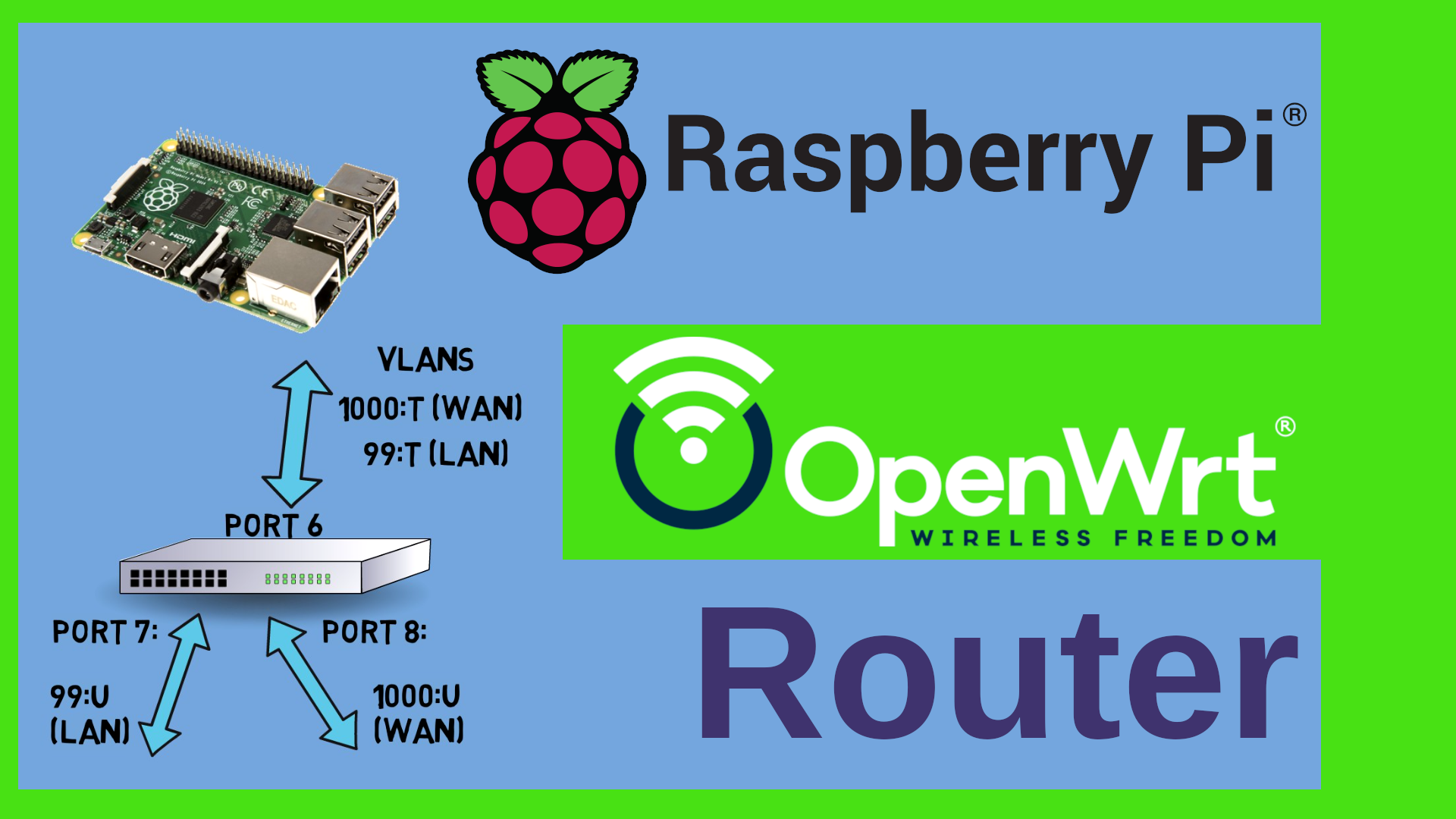
Now let’s see how the config on the internet gateway differs from the config on the so called dumb access points. Let’s start with the internet gateway. That’s the router that connects you to the internet. You can see here that I have three interfaces called IOT, GUEST and LAN. They all have static IP addresses and if we go over to the DHCP tab then you can see that each of those serves IP addresses on their own subnets. Also, each one of those is assigned to its own firewall zones with different policies. Furthermore, there is a WAN interface which is the default gateway. That’s of course how we get to the internet. All other interfaces should NOT have that box ticked. If that main router or internet gateway has Wi-fi then we would also have Wifi SSIDs here under Network-Wireless. Down here you can see which network they are attached to. That’s the link between the Wi-fi and the network interface. The Guest Wi-fi is on the guest network, The IOT on the IOT and so on.
Now let’s have a look at the dumb access points. Setting those up requires a bit more time. I create the same interfaces like on the internet gateway here, just this time I select unmanaged or DHCP client as a protocol. I suggest that you set this to DHCP client in the beginning – even if you want to change it later. That’s actually an easy way to check everything. If everything goes OK, then these interfaces should get IP addresses over DHCP from the main router. If they don’t then something’s wrong. When you create the interfaces on the dumb access points then you don’t assign them to a firewall zone. They will just be bridged on layer 2 – all IP traffic and firewall will be handled on the main router. Leave the “Device” unspecified for the moment – we will link this to the right batman interface later. Now when you set up the Wi-fi’s under network-wireless by clicking again on “add” next to the desired radio then this is where you would actually link the Wi-fi interface with the interface that we have just created. So I would link the M-IOT Wi-fi to the IOT network, the M-Guest to guest and so on. Now for the LAN and WAN. We don’t need a WAN interface on those – we have the WAN interface on the main router. So let’s delete it. The LAN interface in turn should not have a static IP, but rather have an IP served by the main router. So I change the protocol to DHCP client. Do not click on “Switch protocol” – that would commit the change immediately. We need to configure a couple more things. At the moment I am connected to this device with an Ethernet wire. Hence the LAN interface has a device attached, in my case br-lan. I’ll leave it that way for the time being. Just on the firewall setting I remove the firewall zone and on the DHCP Server tab I deactivate the DHCP Server by ticking the “Ignore Interface” box. Click on Save. Don’t Save and apply yet. We might want to check on the devices tab if every Ethernet port is assigned to the right interface. In my case I want both ports to be on the LAN. One port is currently connected to my main router and the other one to my PC. For a dumb Access point they should all be connected to the LAN side, Therefore I change the settings for the br-lan bridge so that eth0 and eth1 are both LAN.
Once I click on Save and Apply here then the following happens: My Access point tries to get an IP address over DHCP from the first router and also my PC gets an IP address in the same range. As now we are both in the same LAN. I need to wait until this goes through. Plenty of time. I have 90 seconds before everything gets rolled back. Once I have the IP address, then I can check on the main router to see which new IP my access point has. And once I connect to the web interface of that Access point then the changes get applied because LuCI has confirmation that we could actually reach it. Otherwise the changes would just have been rolled back.
All that’s left to do on this access point is to stop and disable some services under System-Startup. Namely the dnsmasq, odhcpd and firewall services. That’s it.
Guys, I’ve been rushing a little bit over this as I have covered that part in a lot of videos already. If anything is unclear in this section then please check the related videos. Here’s what we have so far:
we have a main router with a WAN interface, three interfaces called IOT, GUEST and LAN. Potentially three Wi-fis with similar names attached to the respective interfaces. Furthermore we have Access points – basically Wi-fi routers where we have stripped Firewall, DNS, DHCP Server and IP routing – with the same interfaces, but of course no WAN interface. The access points have a Wi-fi mesh and the main router may or may not have one. Now let’s do the B.A.T.M.A.N. part in order to connect everything.
In order to install the batman advanced protocol we can log into the Web UI of our OpenWrt Router or Access Point which is called LuCI, then we go to System-Software. If you type in batman you should see these software packages here. If you don’t see any, then just refresh the list by clicking on update list. The one we are after is the luci-proto-batman-adv package here. At the time of making this video – in April 2022 – chances are that you can’t find that package. The reason is that it is brand new. If it is there, just click on install next to it. If it is not there, then you may download it from my github server – the download location is in the description of the video. In this case please first install the kmod-batman-adv package and once you have done that, click on upload package, browse to the file that you have just downloaded and then click on upload and then on install.
Awesome – at this point you might need to reboot your router or access point – just to make sure that all protocols are available. Once your device is back, then please go to network-interfaces and click on add new interface. If everything went well, then you should have an option “Batman Device” here in the protocol drop down list. Let’s name the interface bat0 and select “Batman Device” as the protocol. Then click on “Create Interface”. You notice there is this additional tab over here named “Mesh Routing”. Let’s click on it. We really don’t need to change many options here. Most default values will probably suit most cases. However I prefer to tick the box “Bridge Loop avoidance” in order to avoid endless loops if ever a packet turns around in circles on the mesh. I also want to select a value for the gateway mode. Set this to “Server” on your Router and to “Client” on the access point. Now click on Save. If you click on the Unsaved Changes icon up here then you can actually see the changes that will be made to the system. Perfect. Adding the batman network is a three step process. We have done the first step by creating the bat0 device. You can actually see this if you go over to the devices tab here. Here it is. Bat0. Back to the Interfaces tab. The next step is to actually create an interface that is linked to the bat0 device and carries the mesh traffic.. Let’s again click on Add new Interface, let’s call the interface let’s say batmesh and select Batman Interface as the type. Please do NOT select the bat0 device in this dropdown here. Leave it blank for the time being! I’ll explain in a second. Once you click on Save then you should get two additional options here. One is called Batman Device – THIS is where we select the bat0 from the previous step. And the other one is “Override MTU” – leave this blank for the time being. I’ll explain it later. Please do not change any of the other values yet. I’ll explain everything. Last step - Now go over to Network – Wireless and this is where we actually link the Wi-Fi Mesh to the batman network. Just keep going. I’ll explain everything. Select your Wi-fi Mesh from the list of Wireless networks and click on Edit next to it. Down here under “Interface Configuration” we can select the network which our Mesh is connected to. In my case that’s the LAN. From this drop down list I select the batmesh network that I have created in the second step. Also – please go over to the “Advanced Settings” tab and untick the box “Forward Mesh Peer Traffic”. We do not want the mesh interface and hence OLSR – Optimized Link State Routing – to determine the paths through our mesh. That will now be handled by batman. Cool. Now click on save and Save and Apply. On Nodes that are connected to other mesh nodes over Ethernet, we would repeat step 2 and create another Batman Interface. In my case I called it Batwire and attached it to an existing bridge called br-mgmt. That’s actually my management network which in turn here on the devices is bridged with Ethernet VLAN 39. You might want to use plain eth0 or an existing VLAN for this – depends on your config really. On OpenWrt Version 19 you can do this as well – Let me show you an example how I run the batman network over an Ethernet wire – in my case this is a VLAN but you could select plain eth0. Just make sure that you DON’T tick the bridge tick box here – the batman interface does not work if it is a bridge itself. You may attach it to a bridge in Version 21 but it does not have to be a bridge itself like in Version 19.
Let’s stop here for a second. We have done a lot of “click here, click there.” Let me quickly explain where we are at this stage. We have now added the B.A.T.M.A.N. advanced device to all routers and access points participating in the mesh. We have assigned the interfaces that carry the mesh traffic to an Ethernet port on the wired portions and to the Wi-fi Mesh on the Wi-fi portions. For Nodes that participate in both ethernet and Wifi Mesh, we have created two Interfaces. So now we have a B.A.T.M.A.N. advanced network spawning our whole network. B.A.T.M.A.N. advanced will take care of all the discovery and routes in that mesh. What we need to do next and actually as a last step is that we bridge the Interfaces and hence the Wi-Fi networks to the right B.A.T.M.A.N. advanced devices. Pretty much the same like with Ethernet VLANs. I have decided to use the following networks on my mesh – and they of course correspond to the VLANs that I have been using in the other videos. 3 for IOT, 4 for guest and 99 for the LAN traffic.
In order to do this we will now assign the right network interfaces to the corresponding B.A.T.M.A.N. advanced device. Let’s actually create a bridge for each one of them. First IOT. I go to Network-Interfaces – Devices Tab and click on “Add Device Configuration”. The type will be bridge. I create a bridge here because we might want to attach multiple interfaces to that device. First bridge is called br-iot. In the bridge ports drop down box I type in bat0 – because the IOT network shall flow over the batman network and then I add dot 3 – because I want to use the network number or VLAN 3 for IOT. That’s it. Save. Do the same with br-guest and bat0.4, then br-lan and bat0.99 – You may use different numbers. I have just chosen them arbitrarily. On the br-lan bridge I have also added the Ethernet ports. Cool – now over to the Interfaces tab. I click on “Edit” next to each interface and make sure that each interface is linked to the right device. Again – br-iot for IOT , then br-guest for Guest and so on. Perfect. Now let’s click on “Save and Apply” and do this on all nodes. What should now happen is that the IOT and Guest interfaces get assigned IP addresses from the main router’s DHCP Server. It might take a minute. Here we go. All good. Do this on all access points and routers. Quick tip here – if you have multiple devices of the same brand, make and model then ou can accelerate the configuration if you take a backup of the first node and restore to the others. You would still have to install the software packages but it will save you a lot of clicks.
If we look the blue print again – here’s what we have just done. The batman interface carries the mesh traffic and we attached all interfaces of Guest, IOT and LAN to the right sub-interfaces or rather VLANs. We now have a working Mesh that can run over Wi-fi or Wire or – like in my case – mixed architectures. Let’s test it.
When I set up the Wi-fis, I had also activated fast roaming or fast transition. You can do that by ticking the 802.11r tick box under Wifi-security. Just chose a 4 digit Mobility domain – which has to be the same on all Access points for a given network – that means it has to be the same on all IOT, then a different value for all Guest and so on. Select FT over the air in the FT Protocol Dropdown. These settings will accelerate the hand over from one access point to another. What I want to do next is that I walk around the house with my mobile phone. The phone should then quickly roam from one access point to another and keep me connected at any time. On the phone I will run an iperf3 speed test and measure the bandwidth. Just before I do that let me show you an important tool of the B.A.T.M.A.N. advanced network. This is a command line utility called batctl. Short for batcontrol. This utility gives me a lot of insight into the mesh. I can for example show all the participating mesh nodes or originators with batctl originators or short batctl o. This shows all my Access points and the router. Or I might want to see the available Internet Gateways in my mesh by typing batctl gwl which is short for Gateway list. Look what happens when I change the gateway bandwidth on my router with batctl gw. The info gets replicated instantly to all nodes. I can do things like show all MAC addresses in the MAC table and even measure throughput between nodes and so on and so on. In order to make this a bit more readable I can actually create a bat-hosts file that would then show host names rather than just MAC addresses. Here’s the output. What I am after is this info here. I want to see the next hop to my Mobile phone. As I walk around this should change. Automatically. Without me noticing. So here on the screen you see the output of the transglobal table showing the next hop to my iphone and down here the iperf3 throughput that I have with my phone. As I walk around the next hop changes and occasionally the speed does – depending on how many nodes I am actually connected to. Now I will be walking around my Wi-fi Mesh which I actually had to extend to my three floors and the garden to make it a bit more real-world size. Everything is on the 5GHz band, so roaming should occur quite frequently here. Just as an overview here’s the complete plan of the Mesh. I have 6 of these Lyra Access points, lyra1 on the 1st floor of my house, lyra2 in the basement, lyra3 at the ground floor level. Plus lyra4, 5 and 6 positioned at windows around the house. I have the router in the middle which does not participate in Wifi. Lyra 1,2 and 3 are wired to the router. Now watch how everything moves. You can see my phone roaming from one mesh node to another in the top window and in the bottom window you can read the throughput from iperf3. Please do keep in mind that the Access points are all inside the house and I am walking around the house outside – it’s all thick concrete walls here, so sometimes the performance drops badly. But this is not meant to be a speed optimization but rather to show the transparent hand off from one node to another. Even though I have noticed some seconds of outage. I might need to check on all parameters such as the Mobility domain for fast roaming and the used channels. Also – using a high 5 GHz channel as the backbone might not be the best solution in my concrete bunker. I would probably be better off with a 2.4 GHz backbone. Last but not least, I have not yet optimized anything for fragmentation – that means that all the MTUs on the whole network are 1500 by default which of course lowers the performance considerably. But I think you get the idea.
So – overall conclusion – The B.A.T.M.A.N. advanced network can be used to spawn a mesh of virtually any size over multiple nodes in a mesh – be it wired or wireless or hybrid. At the same time the B.A.T.M.A.N. advanced driver transforms the mesh into a giant managed switch. You can plug in any interface anywhere to any VLAN on that switch. You could use this to build a Mesh with Wi-fi and wired portions like I just did or – because you can have multiple Gateways on that Mesh – you could use it to build a community mesh – be it a large house with multiple parties or a whole street or a city – it doesn’t matter – everyone could still have their own Wifi name etc. on different VLANs. Just the parties could share all their internet gateways. So rather than having a combat over free Wi-fi channels, you could actually share them in an intelligent way and provide better Wi-fi to everyone.
Having said that – that’s all I wanted to show you today. Thanks for watching. Stay safe, stay healthy, bye for now! Leave me a like and a comment ! Bye bye !